Baja
NARS Baja (2002 – 2008)
The Gulf of California rift forms a geologically young and active plate boundary that links the San Andreas strike-slip fault system in California to the oceanic spreading system of the East Pacific Rise. Although this is a classical example of a transform-rift plate boundary, the tectonic evolution of the Gulf of California and surrounding regions is complex and poorly understood due to a lack of geological and geophysical data. From 2002 to 2008, the Network of Autonomously Recording Seismographs (NARS)-Baja network was installed. It consisted of 19 broadband seismic stations deployed in the Baja-California and Sonora provinces of Mexico.
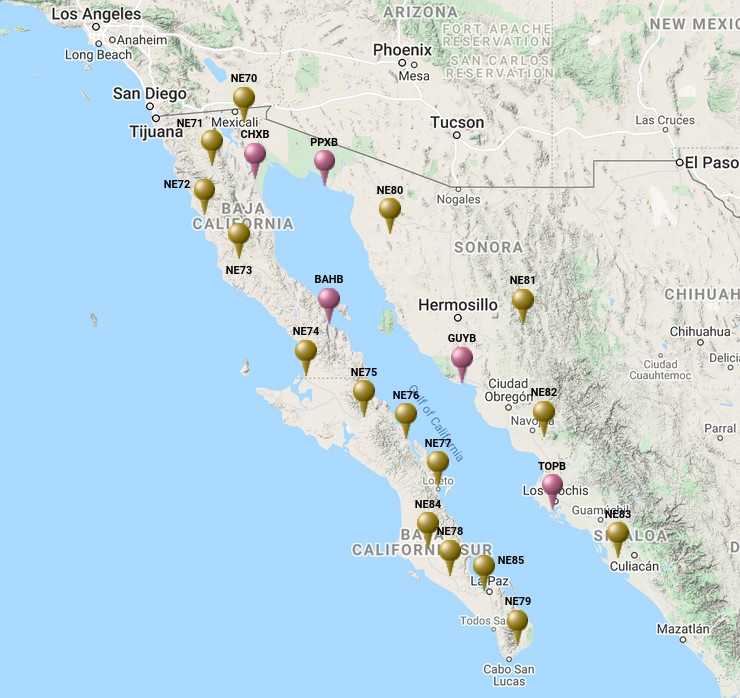
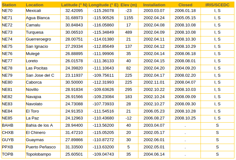
Station list & data
Data of the NARS-Baja project are available through the Incorporated Research Institutions for Seismology (IRIS) under the FDSN network code NR. For requesting NARS data click here. For the NR network station map click here here.
NARS-Baja data are also available from the Southern California Earthquake Data Center (SCEDC).
Overview
Since NARS-Baja surrounds the Gulf of California rift system, it is ideal for constraining earthquake faulting processes and the crust mantle structure of the region. Moreover, NARS-Baja, in combination with permanent Mexican and U.S. arrays, forms a unique linear array in excess of 4000 km that should lend itself ideally to seismological studies of the North American Pacific plate boundary on a larger scale. NARS-Baja is planned to operate for at least 5 years. To promote involvement from the entire research community, the data collected from the stations were made available immediately following routine data quality checks.
The need for a broadband seismic network surrounding the Gulf of California is clear from catalogues of the International Seismological Centre (ISC) and the National Earthquake Information Center (NEIC), which contain an unrealistically low number of earthquakes with magnitudes smaller than 4. Owing to a nearly complete station distribution achieved with NARS-Baja around the Gulf of California, an improved detection level allowed accurate earthquake locations and well-constrained focal mechanisms of moderate (M > 3-4) earthquakes to be determined. It enables to delineate active faults more accurately and improve our understanding of strain release and tectonic deformation in the region.
In addition, NARS-Baja data is crucial for studying the crust and upper mantle structure beneath the entire Gulf of California. While global and continent-scale seismological models suggest that the seismic velocity structure in the mantle beneath the Gulf of California is as anomalous as that of the East Pacific Rise, NARS-Baja data allows us to make models of the crust and mantle with unprecedented resolution. Resulting crustal and mantle models provide new constraints on the nature of this young plate boundary and its transition from strike-slip faulting along the San Andreas Fault system to ocean spreading along the East Pacific Rise. The Moho depth is mapped using body wave coda and short-period surface waves, while the lithospheric and asthenospheric structure are determined using body wave travel times and waveforms and long-period, surface-wave dispersion measurements. The surface-wave data further provide important constraints on anisotropy in the uppermost mantle, and together with shear wave-splitting measurements, mantle flow can be imaged. These are several examples of well-established techniques that can readily be applied, but the NARS-Baja network, especially in conjunction with existing Mexican and Californian seismic arrays, offers ample research opportunities for deep mantle and core studies as well. We hope that our policy of full data availability will encourage many members of our research community to participate in analyzing the NARS-Baja data.
NARS-Baja originated from a desire to combine scientific interest, regional as well as global, with a maximum ease of operation in terms of instrument availabilty, data storage, and manpower. It is a joint effort between Utrecht University (The Netherlands), Centro de Investigación Científica y de Educación Superior de Ensenada (CICESE, Mexico), and the California Institute of Technology, and it consists of 19 broadband seismic stations deployed on either side of the Gulf of California with a 100-150 km station spacing. Every 3 months or so, all stations were visited by CICESE researchers for maintenance and downloading of the data. The raw data were immediately sent to Caltech where, after preliminary quality inspection, full seed volumes were assembled and archived. Both the IRIS Data Management Center in Seattle and the SCEC Data Center at Caltech storer the continuous data that are made available to the community via Web-based request tools.
The NARS-Baja project has been initiated by the following people: Jeannot Trampert, Hanneke Paulssen (Utrecht University), Jeroen Ritsema, Robert Clayton (Caltech), Raul Castro, Cecilio Rebollar (CICESE).
The project thanks its succes to the efforts of the technicians Arie van Wettum (Utrecht University), and Arturo Perez-Vertti (CICESE).
Acknowledgments:
We are grateful to SCEDC and IRIS DMC for agreeing to archive and distribute our continuous waveform data. Funding for this project was provided by Utrecht University, the Dutch National Science Foundation (grant number NWO-GOA-750.396.01), and the U.S. National Science Foundation (grant number EAR-0111650 of the MARGINS program). Maintenance of CICESE broadband stations is partly funded by CONACYT project 37038-T. We also greatly acknowledge the participations of Oscar Galvez, Antonio Mendoza, Luis Orozco and Luis Inzunza (CICESE).
Example: recordings of the 2003/05/26 Honshu event
Equipment
Seismometer
The seismometer used in the NARS Baja project is the Streckeisen STS-2 broad band sensor. The STS-2 is an electronic force-feedback sensor that provides an output signal proportional to ground velocity over a broad frequency range. Three identical obliquely-oriented mechanical sensors are used and standard vertical and horizontal outputs are derived by summing the raw sensor signals within the STS-2. The housing is vacuum-tight and designed to minimize the distortion of the package by barometric pressure changes.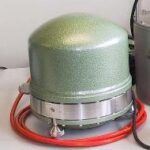 The STS-2 is designed for quick and simple installation, wide temperature range operation, and secure transport, while resolving minimum earth noise levels over the frequency range.
Timing
For precise timing we used the Trimble Acutime 2000 GPS smart antenna. It generates a pulse-per-second (PPS) 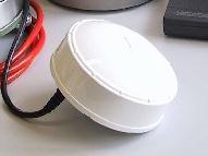 output synchronized to UTC within 50 nanoseconds (one sigma), outputting a timing and position packet for each pulse.
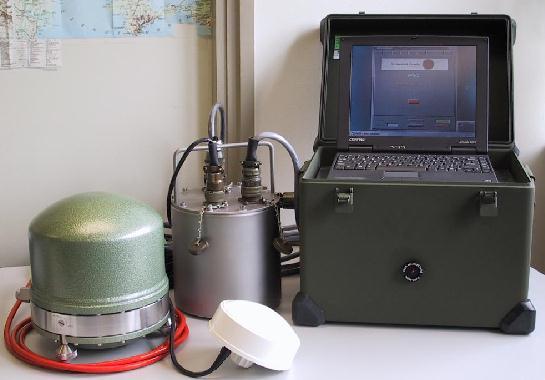
The NARS data logger
The Seismology group of Utrecht University together with the Instrumental group of the Physics department, developed a seismic data logger. 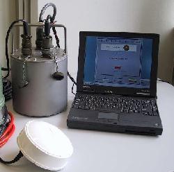 The data logger consists of only two main components: (1) a data acquisition module, which does the AD conversion and timing. (2) an off-the-shelf computer, for all further data processing. Both modules are connected via a standard printer port interface, assuring that the end user has the maximum freedom in computer selection.
Data logger concept
The data acquisition module is connected via a printer port interface to the computer. It provides 6 analog input channels, 6 I/O lines, and controls the seismometer, temperature sensor, pressure sensor and GPS receiver. Each analog input channel is converted with a separate analog to digital converter (ADC). A high precision clock, independent from GPS, time stamps all ADC data. The data from the GPS is also time stamped by the same clock. Both data streams are kept separate throughout the entire data acquisition. Data processing and time correlation between GPS and ADC samples are postponed until the data are processed by the computer. After further filtering and decimation, the data are written in mini-SEED format to disk.
System architecture
Introduction
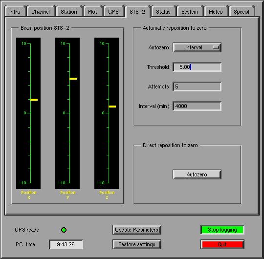
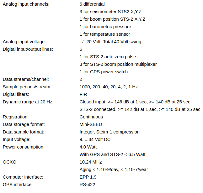
The NARS datalogger has been optimized for the use with the STS-2 seismometer. Three analog channels of the data acquisition module are used for seismic signal logging while one channel is used to measure the individual boom positions of the sensor. This is important for monitoring the drift of the seismometer. One of the I/O lines is connected to the “Autozero” input of the STS-2, allowing, if needed, an automatic zero leveling procedure of the sensor. The two analog inputs left are used for barometric pressure (Vaisala PTB101) and temperature logging (LM35 National Semiconductor). The GPS receiver is the Acutime2000 of Trimble. This receiver has been factory optimized for time synchronization and will deliver time pulses with an accuracy of UTC +/- 100 nsec. Antenna and receiver are built in one housing and the RS_422 interface allows long cable to be used. The computer is a Compaq Armada 100s with DFT screen. This laptop model is quite small and has relatively low power consumption. Computer and data acquisition module are connected via the printer port. Both use the EPP (Enhanced Parallel Port or IEEE-1284) mode for high speed bi-directional data transfer. The operating system of the computer is Real Time Linux.
Data acquisition module summary
The data acquisition module consists of 3 electronic printed circuit boards (PCB’s):(1) The main board, with all ADC’s, high precision clock and control logic, (2) a DC/DC board with the voltage converters, and (3) an analog multiplexer board. All boards are housed in a robust water tight cylinder. External connections are made of quality MIL-5015 connectors.
DC/DC board
The DC/DC board converts any direct current input voltage between 9 and 34 Volt to the appropriate voltage levels used by the data acquisition module. The module also provides the power for connected sensors like the STS-2, pressure sensor and temperature sensor. The main input voltage as well as the 5 Volt output voltage can be monitored by computer software.
Main board
All controller functions, FIFO (First In First Out queue) communication and EPP interface are implemented in programmable logic (Field Programmable Gate Array or FPGA) which makes the design highly robust. One single high precision clock (Oven Controlled X_tal Oscillator or OCXO) is provided for the system logic operation and time stamping of all acquired data (figure 1). Signal from each analog channel is converted with a 24 bits Delta Sigma ADC to an output rate of 1000 Hz. The 6 ADCs are working in parallel. Each sample taken by these ADCs is time tagged with the local clock and stored in the ADC FIFO. Writing to the FIFOs will set status flags like FIFO empty, half full and full. Depending on the FIFO status, the computer will read out the ADC data. GPS is used for absolute timing. In addition to position and time, the receiver outputs a timing pulse (PPS) which is synchronized to UTC. On reception of this pulse, GPS data is time tagged, stored in the GPS FIFO and also read by the computer.
figure 1
Multiplex board
This small board has been added for use in conjunction with the STS-2 seismometer to measure the boom position of the sensors. One analog channel and 3 I/O lines are used for this. Signal changes are so slow that one measurement every 20 or 30 seconds is enough. This allows for the possibility to use only one analog input channel and measure in turn all 3 boom positions. Channel selection is done by computer software by activating one of the 3 I/O lines.
Mechanical
To avoid corrosion in the field, the housing consists of a water tight cylindrical pot with lid, both made of stainless steel. To obtain sufficient delay for environmental temperature changes, the wall and lid are made 5 mm thick. For easy maintenance the PCBs and connectors are mounted directly on the lid.
Computer software
The operating system of the computer is Real Time Linux. Real Time Linux is a hard real-time operating system that can coexist with Linux OS on the same computer. With Real Time Linux it is possible to create real-time POSIX.1b threads that will run at precisely specified moments of time. The computer software is split in two parts, a time critical real-time thread and a normal Linux task (figure 2). Communication between the real-time thread and Linux task is accomplished by reading and writing of software FIFO’s. All communication with the data acquisition module is handled by the real-time thread.
figure 2
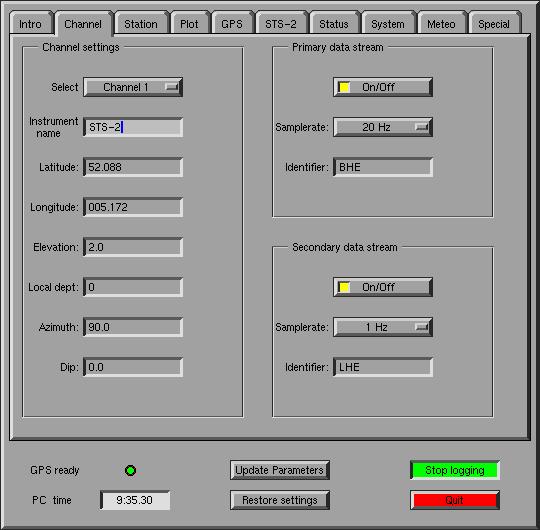
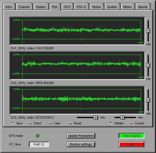
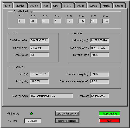
The interface with the user is a graphical X_window based program. The user can change system settings and monitor in real-time the different analog signals. Settings can be changed on the flight and other programs may be run without stopping or affecting the logging process. Some screen dumps are shown below.
Performance
For the ADCs we chose the ADS1210 from Burr-Brown. For high precision applications, Burr-Brown recommends an external reference. Detailed analysis shows that the accuracy of the external reference voltage fully determines the analog quality of the design. None of the proposed voltage references by Burr-Brown deliver sufficient accuracy for our system. With a small modification of the system design, we could improve the quality of the reference to the necessary accuracy. A known noise source in delta-sigma converters is the idle tone. Usually a very low level and long periodic signal at the output, produced by the modulator of the converter. With some extra hardware we have overcome this problem and significantly improved the system accuracy for the longer periods. A dynamic range of more than 140 dB at a period of 25 seconds was obtained.
Site preparation
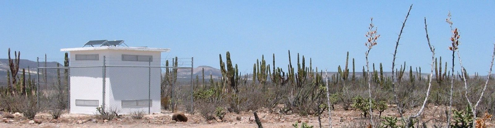
A potentially good site for a broad band seismic station is on hard-rock and far away from cultural noise. However, in remote places, such as Baja California, theft or vandalism of the equipment is a great concern. Therefore the stations have been selected with security as a priority, sometimes at the cost of a higher ambient noise.
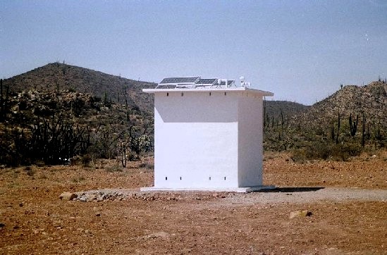
Shelter construction
All stations are housed in a purpose built shelter, made of hollow concrete blocks. Roof and floor consist of reinforced concrete. To avoid ambient noise as much as possible, a seismometer platform is constructed on an outcrop which is decoupled from the structure of the building. Extra attention has been paid to thermal insulation. The inside roof and walls are insulated with 5 cm Polystyrene plates, carefully glued together, forming the insulating inside cabin. Between the Polystyrene wall or roof, an air space was left of 4 cm. In a few places of the outside wall, small gaps are left open to ventilate the air. Outside walls are white and the roof has been painted with sun reflecting paint. A plastic tube guides the cables from the roof to the inside cabin. The entrance door is made of insulated polyester, and where possible located on the shadow side of the shelter.
Positioning
The seismometer should be oriented as close as possible along the geographical NS and EW directions. A magnetic compass measures the direction to the magnetic pole, but has to be corrected for the local declination. Additionally, the presence of metal in the ground or construction and even solar wind can strongly disturb the measurement. To avoid all this uncertainty, we used a gyro compass in combination with two handheld GPS receivers to measure the geographical direction. We used the following procedure.
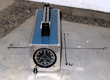 Two people with both a handheld GPS receiver, read the same latitude/longitude on a position P1. Both agree on either latitude or longitude to be kept fixed on their GPS receiver. One person starts walking for approximately 150 meters to a position P2, keeping latitude or longitude to the agreed value. Possibly the person at P1 has to move a few meters to hold the same value. When both persons receive the fixed value, P1 and P2 are marked. Depending on latitude or longitude, the line (P1, P2) represents an exact geographic East/West or North/South line. The gyro compass is exactly positioned along the line (P1, P2) and calibrated. Once the gyro compass has been set, the shelter can be entered to position the seismometer.
The absolute position read on the GPS receiver is not important. Both receive the same satellites with the same error at the same time. The difference between both receivers will decrease the direction accuracy. In practice this is better than 2 meters. To fix ideas, with a 4 m accuracy the error in orientation is only 1.5 degr (atan 4m/150m).
Power
Most sites are located far away from any power supply, therefore solar panels have to be used as a power source. The total power consumption of a NARS station is only 20 Watt. Depending on the local situation, 3 or more solar panels of 55 Watt each are installed on the roof of the shelter. An intelligent charge controller regulates the power and maintains the 2 x 210 Amp Hour solar batteries. With fully charged batteries and a total absence of sun, the station will operate for at least 5 days. Depending on the battery charge, the power monitor will shut down or reboot the data logger system.
Seismometer insulation
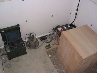
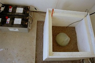 Thermal insulation has a big influence on the overall performance of the broad band seismometer. To achieve this thermal shielding, the sensor is totally covered in sand. To protect the connector of the sensor from dirt, we first placed it in a thin plastic bag. After installation and positioning, a wooden box with a 5 cm polystyrene inside insulation is placed over the edge of the platform.
The box is carefully filled with dry sand and closed with a wooden lid, also insulated with polystyrene. 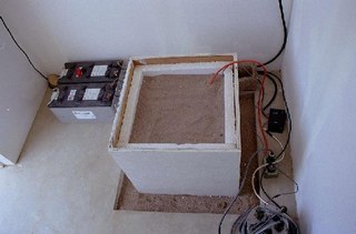 This simple construction has three big advantages: (1) long thermal time constant for the sensor, (2) full access to the seismometer for installation, and (3) easy removal of the sand by just lifting up the box.
 Although the seismometer has been isolated as good as possible, long period temperature and barometric variations are still visible in the seismic signal. We installed a temperature sensor inside the rod hole of each STS-2 and in one station a barometric pressure sensor. The pressure and temperature variations are recorded together with the seismometer signals and can be used for signal corrections.